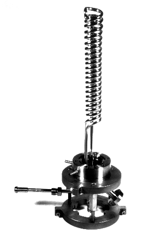
The NH_3 gas is delivered through a tube at the center of the flange to the nozzle, which consists of a circular stainless steel disk held in place by a ring with a d=200 mm hole at the center. The tube holding the nozzle is centered by a circular holder connected to the body of the jet. The skimmer is placed on top of a can that screws into the base of the jet, and is located x_s=1.3 cm from the nozzle. The cryopumping is realized by a circular stainless steel tube wound all the way from the base of the jet close to the skimmer and back, exiting through the side of the base. Welding ensures a vacuum tight exit. Electrical feedthroughs are provided for a heater and a thermocouple, as well as a feedthrough to a vacuum gauge to measure the background pressure P_b. The heater is placed about 5 cm from the nozzle by winding a tungsten wire around a circular ceramic spacer. The thermocouple is mounted close to the heater.

Figure 8: Photograph (Ref. 23) of NH_3 Jet Prototype #1
Table of Contents