The substrate temperature T_sub can therefore be determined as follows. At the balance point, with no growth taking place (no NH_3 flux), the equilibrium condition is given by:
(45) ![]()
First the vapor pressure equation is written as a function of flux instead of pressure. The vapor pressure equation represents the equilibrium at which the incoming flux Gamma_(in (v.p.)) equals the outgoing flux Gamma_evaporate written as:
(46) ![]()
According to kinetic theory the particle flux Gamma_(in (v.p.)) of an ideal gas striking a unit surface or crossing an imaginary plane of unit area from one side is
(47) ![]()
where n is the particle density and v the average velocity. The average velocity is given by:
(48) ![]()
Substituting equation(48) into (47) yields:
(49) ![]()
The particle density n is related to the pressure p by:
(50) ![]()
Substitution into equation (49) yields:
(51) ![]()
Using
(52) ![]()
results in:
(53) ![]()
The vapor pressure equation is shown in Table 9 and given by
(54) ![]()
or, including the conversion from (atm) to SI units (Pa):
(55) ![]()
Substitution into equation (53) yields:
(56) ![]()
where in our case T=T_sub.
The incoming flux Gamma_in can be determined by observing the RHEED oscillation frequency during AlAs, GaAs, or InAs growth. The calibration is typically an exponential curve fit of (ML/s) vs (Source Voltage in mV) and represented by the equation:
(57) ![]()
The conversion of (ML/s) to incoming flux Gamma_in assuming unity sticking coefficient is given by
(58) ![]()
where a is the conventional unit cell lattice constant of AlAs, GaAs, or InAs. Substitution of equation (57) into (58) yields:
(59) ![]()
Finally, equating the incoming flux to the evaporating flux given by equation (59) and (56) results in:
(60) 
As an example let us take Ga whose molecular mass is W=0.06972 kg/mole. The lattice constant for GaAs is a=5.65Å. In this example the constants D and F have been determined from the GaAs calibration of the Ga source to be 5.7787x10^-10 and 1.1315, respectively, as shown in Figure 32a. The constants A, B, and C for Ga from Table 9 are 6.754, -13984, and -0.3413, respectively. The (mV) setting used for the Gallium flux at the balance point was 20.50 mV. In this example equation (60) becomes
(61) 
and is solved numerically or graphically as shown in Figure 30. The result is that the balance point substrate temperature T_sub corresponding to a Ga flux Gamma_in given by a source voltage of 20.50 mV is 1070 K, or 797°C. If the thermocouple read 920°C we have an offset of 123°. By similarly determining the balance point for several fluxes the thermocouple can be calibrated over a wide range of temperatures. A typical curve for a clip mounted 1'' GaN sample backed with 5000 Å of Ti is shown in Figure 31. Note that the calibration can be performed much more accurately than shown (+-5°C) if more time is taken to determine the balance points (to about 1°C).
Figure 33 shows the balance point temperatures for Ga, Al, and In, as a function of flux (in ML/s for GaAs, AlAs, and InAs growth), which comes in handy in conjunction with Figure 32 to determine growth conditions during an experiment.
Another example is AlN. So far we failed to observe the balance point for AlN due to insufficient surface quality. Typical values for constants D and F for our Al source are 1.5259x10^-10 and 0.017083, respectively (see Figure 32b). Note that those constants were obtained from a curve fit of (ML/s) vs source temperature ("°C" display), therefore this value is to be inserted instead of (mV) in equation (60). The lattice constant for AlAs is a=5.66Å, and the molecular weight is W=0.0269815 kg/mole. Therefore the equation to be solved for Al is
(62) 
and some typical balance point values are given in Table 10.
Typically our initiation layer of AlN is grown at 1300 source display. This corresponds to a balance point substrate temperature of T_sub=848°C. Since our substrate heater only reaches display temperatures of 1000°C this calculation shows that the offset can not be larger than 152° degree for AlN growth to occur under the conditions given (assuming the Al evaporation is much larger than the conversion to AlN as argued elsewhere). Our offset is typically about 120° with the latest sample holder models and substrates used, and it can be seen that we are growing above the balance point for the conditions given. These results agree well with our observation that we have to grow close to the highest attainable substrate temperatures to obtain good AlN films. All attempts to grow AlN below the theoretical balance point failed so far as predicted.
As a comparison Figure 34 (and also Figure 37) displays the vapor pressure of Al, Ga, and In. Noting that the In vapor pressure is much larger than that of Ga it might prove to be necessary to grow InN at a lower substrate temperature if possible. This follows the general trend since AlN is usually grown at substrate temperatures higher than GaN. It is also known that InN decomposes rapidly above 500ºC, making high temperature growth impossible, as verified experimentally by our group at 700ºC.

Table 9: Vapor Pressures of Liquid Al, Ga, and In (Ref. 41)

Table 10: Typical Balance Point Temperatures for Al
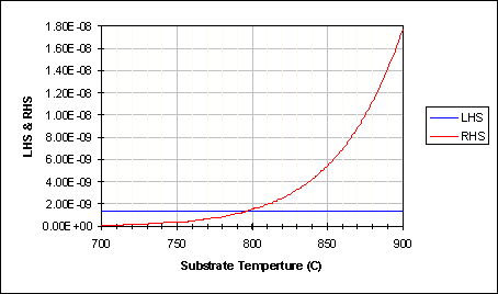
Figure 30: Example: Substrate Temperature Calibration from Equation (61)
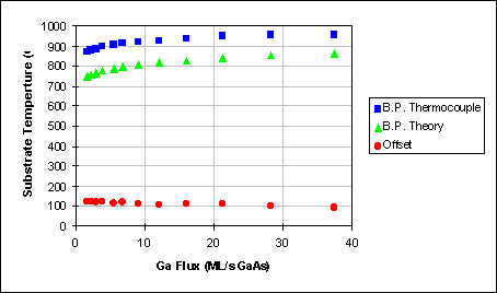
Figure 31: Typical Substrate Temperature Calibration
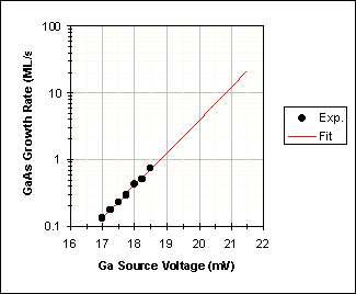
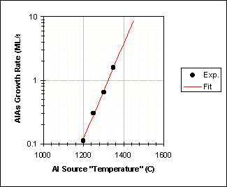
Figure 32: Ga and Al Flux Calibration (Currently)
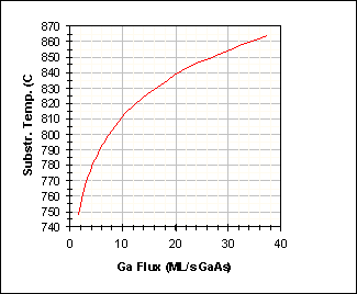
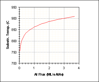
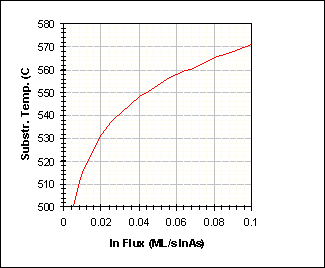
Figure 33: Balance point substrate temperatures for Ga, Al, and In, as a function of flux
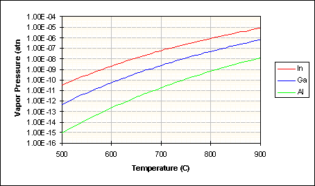
Figure 34: Vapor Pressure of Al, Ga, and In
Table of Contents