Journal of Undergraduate Research in Physics, 11, 2, 1993, p. 37-41
Marsh White Award for Best Paper
We tested our system on a 10 nm Fe on InxGa1-xAs (x=.17) magnetic thin film. The substrate on which the Fe film resides was designed to eliminate stress in the film. Usually, magnetic thin films undergo stress when they are put on a substrate, which in turn effects their magnetic properties. By trying to create a substrate that closely matches the crystalline structure of the thin film, these stresses can be minimized. The magnetic properties of the thin film then can be explored in an unstressed state.
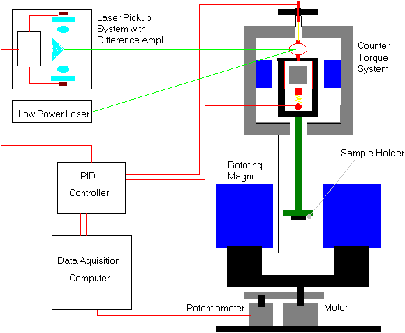
To determine the torque placed upon the sample, the mirror on top of the coil was used. A laser beam was directed at the mirror and reflected into a laser pick-up system. It consists of a prism that split the incoming beam into two components, both falling on separate photo resistors. Any difference in illumination of the photocells is detected and send to a Proportional, Integral, Differential (PID) controller, whose purpose is to provide just the right amount of current to the coil to counter-balance the torque placed upon the sample. The counter-balancing current going through the coil was proportional to the torque on the coil. This current, or respective coil voltage, and the position of the magnet is detected by a data acquisition computer. Graphing the coil voltage versus the position gave us the torque acting on the sample as a function of the direction of the external field.
Figure 1: Overview of the torque magnetometer system.
The magnet was mounted on a rotating platform, which was coupled by a step down gear box to a stepper motor. The stepper motor was driven by a controller from a kit which was modified to be stepped manual or by the computer. The same gear that was connected to the gear box of the stepper motor was connected to another gear (1:1 ratio). This gear is connected to a 10 turn 500 Ohm precision potentiometer. We determined the angular position of the magnet by placing 30 VDC across the potentiometer and measuring the voltage at the center tap.
A coiled gold strip was attached beneath the coil to a fixed pin on the housing. The two gold strips also function as the leads to the coil. The coil could be rotated by placing a voltage across the two gold leads. A bracket was mounted around the coil, supporting a fiberglass rod. The rod led through a drilled hole in the housing to the sample holder between the pole faces of the rotating magnet. An outer 1'' aluminum tube was connected to the housing of the torque galvanometer. The outer tube serves to protect the sample holder from air currents as well as local temperature changes. Two leads went from the gold wires to the input of the PID controller.
The PID controller works as follows. When the laser pick up system reports a voltage different from zero, the linear amplifier responds to supply a linear counter torque to the coil to correct the offset. If only the linear amplifier were used, the system tends to oscillates around zero voltage and the laser pick up system tends to lose the laser beam. To compensate for this, a differential amplifier responds to the rate of change of any deviation from the zero point. As the oscillation tends to get bigger, the differential amplifier outputs a larger correction voltage to suppress these oscillations. The integral amplifier was used to compensated for effects that cause the laser beam to slowly float away from the center of the prism.
The PID controller has controls for the input resistance (capacitance), feedback resistance (capacitance), and zero offset for all the amplifiers. Therefore, the gain of all these components can be adjusted to optimize performance.
The data acquisition was done by a 286 computer with an analog/digital card (Ref. 4). This card could also provide the signal for the stepper motor if we choose.
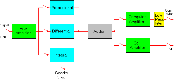
Figure 2: Schematic diagram of the PID-Controller.
The period of a torsion harmonic oscillator is:
(1) ![]()
where I is the moment of inertia and k is the torsion constant. Substituting the moment of inertia of a disk:
(2) ![]()
where d is the diameter of the disk and using Equation 1 to find k yields:
(3) ![]()
The torque required to displace the oscillator an angle theta from equilibrium is:
(4) ![]()
When a current i is placed through the coil, a torque:
(5) ![]()
is exerted on the system. Combining equations 4 and 5 gives a way to determine the constant c:
(6) ![]()
The results of the calibration are shown in Figure 3.
Using Ohm's law, Equation 5 becomes:
(7) ![]()
The voltage V, read by the computer, is just the gain of the amplifier (g) times the voltage across the coil. Equation 7 then becomes:
(8) ![]()
The calibration constant alpha for our apparatus was determined to be (1.8+-0.1) x 10^-8 Nm/V. Torques as small as 1x10^-9 Nm could be measured with our apparatus. This compares favorable with results obtained by other groups (Ref. 5).
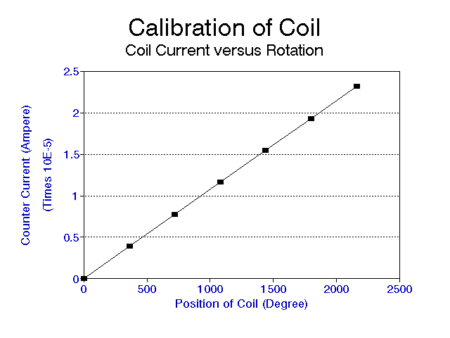
Figure 3: Calibration of the coil by plotting the counter current versus the rotation of the gold strip.
Data were taken by rotating the magnet around the sample by 360º. Since every complete turn was symmetric around 180º, we averaged both 180º parts to reduce noise.
The total magnetic energy density for a cubic crystal can be written as (Ref. 5):
(9) ![]()
where K_1 is the cubic anisotropy constant and the alpha_i's are the direction cosines of M relative to the cubic axes of the Fe lattice. For a thin film, the magnetization is confined to the plane of the films, so we obtain:
(10) ![]()
where phi is the angle that the magnetization makes with the [100] axis and phi_h is the angle that the applied field makes with [100] axis shown in Figure 4. Using some trigonometric identities, we can show that:
(11) ![]()
We will neglect the constant term since the zero of energy is arbitrary.
For our experiment, we applied a large enough magnetic field so that M was al-ways saturated along the direction of the applied field H (phi = phi_h). Thus, the MH term is also constant and will also be neglected in the derivation that follows.
The torque per unit volume in the external field is:
(12)![]()
This is the rotational analog of the force being minus the gradient of the potential energy. Using equation 11 gives:
(13)![]()
This implies that the torque vs phi curve should be four fold symmetric and that K_1/2 the amplitude of the curve. However, our data shown in Figure 5, was not four fold symmetric. This leads us to consider the possibility of a stress induced two fold (uniaxial) anisotropy, characterized by an anisotropy constant K_u. This term increased the energy required to align the magnetization in a direction phi_u relative to the [100] axis. This term is common in magnetic films grown on lattice mismatched substrates. The energy density becomes:
(14)![]()
and the corresponding torque per volume becomes
(15)![]()
Figure 5 shows typical data at a 0.2 Tesla field. The curve was fitted by using the first 2 coefficients of a Fast Fourier Trans-formation (FFT) of the original data. From the Fourier coefficients and the nominal volume of the sample, assuming the 10 nm thickness is correct, we used Equation 15 to find that K_1=8.54 x 10^4 J/m^3, K_u=2.41 x 10^4 J/m^3 and phi_u=47º.
The value of K_1 is about a factor 2 larger than the accepted value for bulk Fe. Typically K_1 in films decreases slightly as the thickness decreases. We attribute this discrepancy to the difficulty in accurately determining the thickness of these very thin samples. The large value of K_u relative to K_1 is also surprising, considering the idea for growing the films on a lattice matched substrate was to minimize stress induced uniaxial anisotropy. The direction of the uniaxial anisotropy, in the [110] direction (phi_u=45º) is consistent with results of studies of Fe grown on GaAs.
From Equation 12, one can obtain the magneto static energy from the torque curve by direct integration. Figure 6 shows the magnetic free energy for the same data.
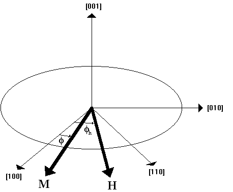
Figure 4: Diagram of the applied field H and the magnetization M with respect to the crystal axes.
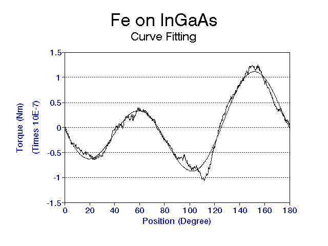
Figure 5: Torque versus angle at 0.2T. The smooth curve is a fit to the data using 2 terms of a Fast Fourier Transform.
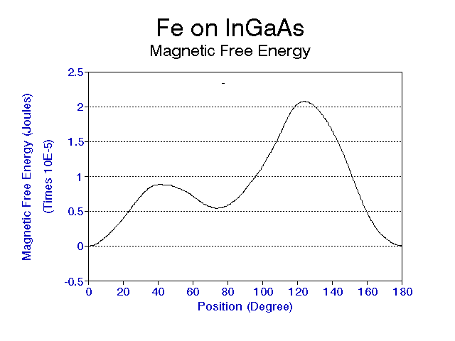
Figure 6: Magnetic free energy versus angle.
Fe crystal alone exhibit no uniaxial anisotropy, but a four fold symmetry with four preferred directions of magnetization (easy axes in the [100] plane). When the film is placed on a substrate, it undergoes stress, which dramatically changes its magnetic properties. The Minnesota group tried to eliminate this stress by placing the film on a substrate with the same lattice characteristics as the Fe. Since we did not see the four fold symmetry, we conclude that either factors are present in thin films other than stress which influence their magnetic properties, or that the substrate was stressed after all.
Special thanks go to Kris Beard, who did all the necessary machine shop work to make this project possible.
2. G. Aubert, J. Appl. Phys., 39, 1968, p. 504
3. General Electric 22 PC 203 stabilized power supply.
4. IBM 286 computer with an IBM DACA analog/digital card. The data acquisition software used was Unkel Scope by MIT, version 3.10.
5. C. M. Williams, et al., J. Magn. Magn. Mat., 110, 1992, p. 61
Back to my home page